Ammonia leak at Alberni Valley Multiplex
Incident Investigation
Ammonia Leak at Alberni Valley Multiplex
November 3, 2019
Reference Number:
II-935221-2019 (#15840)
Location: Port Alberni, BC
Regulated industry sector: Boilers, Pressure Vessels & Refrigeration - Refrigeration system
Incident Overview
A new direct expansion chiller was installed at an ice arena to replace an existing chiller. After almost 20 weeks of service, an ammonia leak was detected, which released ammonia into the machinery room. The low level (25 ppm) ammonia alarm sounded and the ventilation system was activated to continuously evacuate vapours to the outdoors while the location and nature of the leak were investigated.
The plant remained operating for approximately two days in this leaking condition before the source of the leak was found. The source was found to be a crack in the chiller shell. The plant was shut down by the City on order from Technical Safety BC due to the uncontrolled nature of the leak and due to uncertainty around the condition of the chiller vessel.
Impact
Injury
- Quantity of injuries: 0
- Injury description: None
- Injury rating: None
Damage
- Damage description: Cracking in the shell of a direct expansion chiller vessel resulted in an uncontrolled ammonia leak.
- Damage rating: Moderate
Incident rating: Moderate
Site, System and Components
The refrigeration system contains ammonia and provides a chilling effect to the brine by evaporation in a chiller (Figure 1 & Figure 2). The cooled brine is circulated under the ice surface to maintain its frozen condition.
Figure 1: Schematic diagram of incident chiller showing the general flow direction of brine and ammonia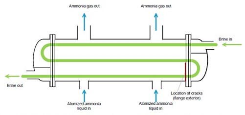
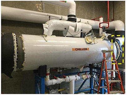
Figure 2: Location of weld failures along 180° of the circumferential shell to head flange weld.
The failure occurred in a relatively new chiller that had been in use for approximately 20 weeks in the refrigeration plant of a skating rink complex.
The chiller involved in the incident is known as a direct expansion chiller. This chiller design is unique in that it requires a relatively low charge of ammonia compared to traditional flooded chillers. However, the ammonia charge in the new chiller was still sufficient to cause serious harm if an uncontrolled release occurs. This is the first chiller of this design commissioned in British Columbia.
The basic design of the chiller includes a cylindrical shell sealed at each end by hemispherical caps (“heads”). These heads are bolted to the shell. To facilitate fastening of the heads, flanges are welded to both ends of the shell to accept the heads. The ammonia leak occurred in the flange-to-shell weld on the north end of the chiller vessel.
Failure Scenario(s)
At 6 am on November 3, 2019 an ammonia leak reached 25 ppm which activated an alarm in the ammonia detection system.
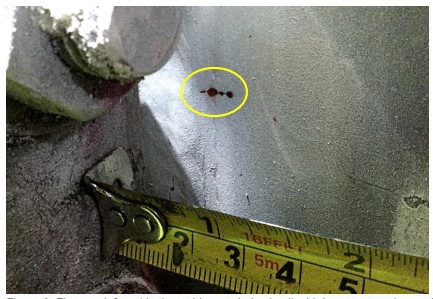
The source of the ammonia leak was found on November 5, 2019 to be coming from a weld crack in the chiller vessel (Figure 3)
Figure 3: First crack found in the weld, revealed using liquid dye penetrant inspection. The crack was 0.250-inches-long and extended from the weld into the parent material.
The weld crack that allowed ammonia to leak was one of multiple internal cracks found in the chiller. One of these cracks grew while the chiller was in service due to stresses from normal operation until the crack penetrated the vessel shell, releasing ammonia into the room.
Cracks can form inside welds during manufacturing if certain precautions are not taken. Precautions that can reduce the risk of cracks forming after the weld was completed include welding procedures that avoid formation of internal defects and high residual stresses.
Quality control test procedures such as ultrasonic testing are available to detect internal weld deficiencies. These procedures were not included in the manufacturer’s quality control and quality assurance plans.
Stress corrosion cracking is also a possible cause of failures at this weld location. This can be avoided with manufacturing procedures that include post-weld heat treating and operating practices that include adding water to anhydrous ammonia.
Facts and evidence
Equipment
This facility originally had a conventional flooded chiller installed. It was replaced with the new direct expansion chiller in June 2019. The volume of liquid ammonia in this direct expansion chiller was limited to a charge of 45 pounds of ammonia which is an amount significantly reduced from the conventional flooded chiller. However, a sudden and uncontrolled release of ammonia can still be hazardous to life and health. The new chiller was commissioned on June 18, 2019. Manufacturer’s documentation provided the following information.
Chiller manufacturing details:
- Constructed in 2018 in the United States to ASME Section VIII, Division 1 and registered with the National Board of Boiler and Pressure Vessel Inspectors.
- The vessel was designed to sustain a maximum pressure of 250 psi (pounds per square inch) on the shell side (ammonia side) at temperatures between -29° and +93° Celsius (-20° F to 200° F).
- The nominal thickness of the shell is 0.375 inches and the tubesheet is 1.5 inches. Both are fabricated from normalized carbon steel, ASTM SA-516 Grade 70N. This is a widely accepted material for construction of pressure vessels.
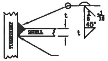
- The welded joint between the head flange and shell was a full penetration groove weld with a 0.375-inch fillet weld (Figure 5). The weld is deposited using a manual gas metal arc (GMAW) welding process with a short circuiting mode of transfer for the root pass and spray transfer mode for the fill and cap passes. The welder holding the welding gun applies the weld when the weld joint is in a flat position while the vessel is rotated. The welding procedure is qualified to ASME Section IX with a minimum pre-heat and maximum inter-pass temperatures of 16° Celsius and 204° Celsius respectively.
Technical Safety BC’s investigation found that post-weld heat treatment (PWHT) was not performed on this chiller as it was not a requirement of the ASME manufacturing code used. The advantage of post-weld heat treatment is that it relieves stresses which can prevent the weld from becoming brittle and can help resist cracking.
During welding, a tack weld is used to position the flange at a specified distance from the shell. The ASME code requires that these tack welds be removed or the edges grinded before the welder applies a welding bead.
The International Institute of Ammonia Refrigeration (IIAR-2) provides recommendations to PWHT chillers to remove residual stresses normally created during a welding process. Although these stresses should typically not pose a problem, it is left to the discretion of the manufacturer (designer) to determine if PWHT is needed for their specific vessel and refrigeration process.
IIAR-2 is not an adopted code in BC. The adopted code, CSA B51, exempts refrigeration type anhydrous ammonia pressure vessels from PWHT. However, the application of PWHT remains at the discretion of the manufacturer.
Weld quality assurance techniques such as ultrasonic testing were not performed and were not specified by the code of construction. Ultrasonic testing is used to reveal cracks internal to welds that would not be detected by the dye penetrant testing used by the manufacturer.
The manufacturer opted for a pneumatic test with nitrogen rather than a standard hydrodynamic test using water. The nitrogen was applied at 275 psi for 30 minutes upon completion of construction; the vessel passed this test. Nitrogen is an inert gas that can fully displace oxygen from the vessel using a gas that prevents corrosion. To satisfy the ASME code requirements for this alternative test using gas (i.e., nitrogen) all shell joints including the two shell-to-head flange welds were tested with liquid penetrant with acceptable results.
The installation of the chiller in the refrigeration plant of the ice skating facility was carried out by a licensed contractor under an installation permit.
Chiller installation details:
- Upon installation the chiller was pneumatically pressure tested at 275 psi for two hours and 34 minutes, then held overnight at 200 psi and then for 10 days at 100 psi, with successful results. Compressed air was used up to 110 psi followed by nitrogen up to the test pressure of 275 psi.
- Upon completion of the pressure test, the system was evacuated and placed under a vacuum for approximately 14 days. The purpose of this procedure is to remove any gas or liquid contaminants. This procedure also provides an indication that the system is airtight. No indication of leaks was noted during the test.
- Following the vacuum procedure, a charge of new anhydrous ammonia vapour was added and the chiller system was started on June 28, 2019.
Plant operational details:
- The chiller maintains brine temperature levels in the range of -6° to -15° C.
- The chiller is subjected to relatively low in-service stresses due to an operating pressure below 50 psi. The chiller is protected from overpressure by a pressure relief valve set at 250 psi.
- When the low level ammonia alarm is activated at 25 ppm, the owner contacts a refrigeration contractor to investigate the leak. The owner’s emergency procedure does not require evacuation of the building unless the ammonia levels are above 200 ppm.
Failure Event
On Sunday November 3, 2019 at 6 a.m. an ammonia leak reached 25 ppm which activated an alarm in the ammonia detection system. The ice facility operator responded immediately by activating the high speed fan to safely evacuate the vapours from the machinery room to the outdoors. At 11:45 a.m. the ammonia levels were noted at 80 ppm. The refrigeration technician arrived on-site at 1 p.m. and investigated the leak under self-contained breathing apparatus at 1:10 p.m. The refrigeration technician located the source of the leak at 1 p.m. on November 5, 2019. The leak was identified to be originating from the shell-to-inlet head flange circumferential weld on the direct expansion chiller.
The chiller continued to operate with ammonia leaking while the refrigeration contractor was looking for the source of the leak. Two days later. on November 5, 2019, the incident was reported to Technical Safety BC by an arena patron and the plant was shut down due to the nature of the uncontrolled leak.
Weld failure assessment:
A company was retained by the refrigeration contractor to conduct non-destructive testing to locate the source of the ammonia leak. Visible liquid penetrant inspection (LPI) conducted on the shell-to-inlet flange circumferential weld identified a 0.250-inch-long crack originating from the weld and extending into the base metal of the chiller shell (Figure 3). The crack was located at the 9 o’clock position (viewed from south end of vessel) and was perpendicular to the weld, as shown in Figure 3.
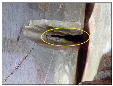
The full size of the crack through the weld and shell was determined by sequential grinding and LPI at 1/16-inch-deep to 1/8-inch-deep intervals. This revealed the crack to be subsurface to the weld extending from the flange into the shell of the chiller as shown in Figure 4. The final crack length was measured to be ¾-inch long and extended fully through the wall of the shell. It was evident from these inspection results that the crack started inside the weld and propagated to the surface over time. This raised suspicions that other internal cracks could be present. Ultrasonic testing is commonly used to detect the presence of internal cracks in these cases. The refrigeration contractor hired a welding contractor to repair the weld crack but did not conduct ultrasonic testing to determine if any more cracks were present.
Figure 4: Larger internal crack (from figure 3) visible after surface grinding. The crack was approximately 0.750-inches-long long and extended up to the flange.
The contractor hired a non-destructive testing (NDT) firm to inspect the repaired weld. Magnetic particle inspection (MPI) was conducted on the root pass and liquid penetrant inspection (LPI) on the final completed weld. No indications of surface cracking were found in the weld repair.
A pneumatic pressure test was carried out at 275 psi and no leaks were found on the repaired weld. However the test identified another crack indication approximately 3 inches away from the first crack on the same weld bead. This second crack was also repaired. This second weld crack increased concerns over the weld manufacturing quality of this new chiller vessel. Weld cracks in a chiller shell should not be expected in relatively new chillers and longitudinal cracks of this nature are highly unusual. Therefore, before placing the chiller back into service and risking another ammonia leak, Technical Safety BC determined that a more detailed examination of the weld quality was warranted.
A professional engineering and testing firm was engaged to conduct detailed ultrasonic inspection of all the welds in the chiller to determine if there was any further cracking or if there were other weld discontinuities.
Causal Investigation
A professional engineering and testing firm conducted an analysis to determine the cause of weld cracks and provided an assessment of all the welds to verify the integrity of the vessel. The initial NDT weld inspection involved testing for surface cracks only. However, the first two cracks were found to have extended all the way through the internal welds. To determine if there was any internal cracking, shear wave ultrasonic testing (SWUT) was used and LPI was completed on all shell circumferential and longitudinal weld joints to check for surface cracking. The SWUT revealed an additional nine subsurface crack indications on the lower half of the same circumferential weld containing the first two cracks.
A total of 11 weld cracks were found in the same weld (Figure 5 & Figure 9). No deficiencies were noted during examination of the other welds in the vessel. Progressive grinding of the weld in the ten new locations found large internal cracks of a similar nature to the original weld failures, being longitudinal into the chiller shell (Figure 6 & Figure 7).
Figure 5: Location of 10 weld cracks found by ultrasonic testing. (Source: Acuren report)
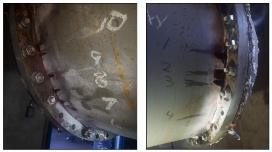
Figure 6: Large internal cracks found when welds ground to reveal inner shell surface. (Source: Acuren report)
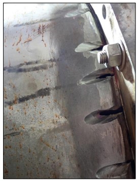
Figure 7: Close up view of typical weld crack size at the inner shell surface. (Source: Acuren report).
Figure 9: Location of 11 weld cracks found and weld joint detail between the shell and flange. (Source: Acuren report)
Repairs were carried out in a similar fashion at all crack locations until all 11 cracks were repaired. The steel was pre-heated prior to each weld pass to reduce residual stress and promote good weld quality. Gas tungsten arc weld (GTAW) and shielded metal arc welding (SMAW) processes were used as preferred techniques for good weld quality. The chiller vessel was successfully pneumatically tested at 275 psi to confirm that the welds were sufficiently repaired. All of the welds in the chiller therefore passed inspection and the chiller was structurally sound.
Failure Analysis
The chiller manufacturer’s analysis of the failure determined that the cause of the weld cracks was stress corrosion cracking (SCC). This conclusion was based on the following:
- Anhydrous (water-free) ammonia was used, whereas the ammonia should contain at least 0.2% water to inhibit SCC;
- Oxygen may have contaminated the ammonia, as oxygen is known to promote SCC in ammonia chillers. The ammonia was not tested to verify the presence of oxygen.
An independent failure analysis was conducted by professional engineers and metallurgists to determine the cause of the weld failures. All of the possible causes of weld cracking in this vessel were considered. This analysis process identified and evaluated two potential causes of weld cracking:
- Environmental cracking (SCC); and
- Manufacturing procedures and omissions.
The independent professional engineers’ report concluded and presented evidence that the chiller weld failures were due to a combination of factory weld cracking followed by low cycle fatigue cracking. Given the uniform spacing of the cracks, it is possible that some of the cracks may correspond with tack welds in the assembly of the flange to the shell. The root cause and contributing factors were identified and detailed in a failure analysis report (see Appendix B).
The factors that did not support SCC as a possible cause in the engineers analysis include the following:
- Ammoniacal SCC follows sustained static stress in mild steel, such as stress present in the heat-affected zone of welds with high residual stresses. Such cracks due to SCC are often oriented parallel to the weld bead. The weld cracks found in the chiller shell were oriented perpendicular to the heat-affected zone and propagated in a straight line with no visible branching (Figure 4).
- Ammoniacal SCC has a distinctive branched pattern. The weld cracks found in the chiller followed a straight pattern with no branching. The presence of fine cracking associated with SCC was not confirmed given that testing at this microscopic level would require destructive examination of the chiller.
- Ammoniacal SCC requires oxygen to be present in the ammonia. The chiller commissioning process followed by the installation contractor was designed to remove any oxygen or moisture from the ammonia. Further, fresh anhydrous ammonia was installed when the chiller was first started. The refrigeration plant is designed to prevent oxygen from entering the system during operation.
- SCC would typically affect all of the welds in the vessel. The cracks found in this chiller were all located at one end, in the same weld.
The manufacturer provided further information in support of SCC. All of the weld cracks were found on the lower 180° of the circumferential weld. SCC is known to occur in the lower quadrant of flooded chillers where the weld is in constant contact with liquid ammonia, but the direct expansion chiller used in this case is not flooded with ammonia but rather uses a smaller amount of ammonia that is sprayed onto the brine tubes and exhausted from the top of the chiller. Although in a direct expansion chiller, it is not flooded with ammonia there may still be a film of liquid ammonia on the bottom half of the vessel. Therefore, it may still be possible for SCC to occur preferentially on the bottom half of the vessel.
Although the liquid film may be present on the bottom half of this chiller, the cracking was found at one end only. The manufacturer stated this may be due to the temperature difference within the chiller that can cause (a) increased wetting of ammonia at one end of the chiller, and/or (b) the chiller being 2° C warmer at one end which can increase the rate of corrosion reactions.
Weld and crack characteristics:
Weld cracks can be small and impossible to detect with the naked eye, which is why LPI is typically used to reveal surface cracks using a coloured dye. This testing was completed during the weld repair to confirm there were no cracks on the multiple weld passes. The chiller manufacturer reported that no testing was conducted on the internal weld passes when the vessel was constructed. Therefore, it may not have been possible for the manufacturer to detect internal cracks before they were covered by overlaying weld passes. However, overlaying weld passes may also re-melt and rejoin surface cracks in the underlying weld pass.
Cracks in the internal weld passes can occur due to inadequate control of the welding process resulting in high residual stresses remaining in the weld after manufacturing is complete. The exact cause of the cracks is not known but weld process control would be suspect. Welding process control problems can include a number of factors due to machine settings or malfunction (e.g. inadequate pre-heat inter-pass temperatures) and human error while manually applying the root pass and all of the overlaying weld passes.
The manufacturer reported that the shell-to-flange weld was performed in a rotating device where the welds are performed in a flat position. This is the preferred weld position for a uniformly placed weld. Residual stresses tend to be magnified toward the end of each circumferential weld pass which could result in a point of high residual stress where each weld pass overlaps itself. Partial stress relief would be provided by multiple weld passes.
The manufacturer used a gas metal arc weld (GMAW) method for the root pass (first weld) in this welded joint. A warning published by the National Board of Boiler and Pressure Vessel Inspectors states this process has a tendency to create “cold lap” defects if not applied by a skilled welder using the correct technique. The GMAW process is also known for its propensity to produce lack-of-fusion defects and is normally not recommended for pressure vessels unless the joint is back welded (back welding was not specified for the incident chiller). If not properly performed, GMAW can cause residual stress.
The high residual stresses can cause cracks to form or cause existing cracks to grow and propagate to the surface during operation. Operational stresses from thermal expansion and contraction as well as internal pressure were introduced during the four months of operation. This can cause the internal cracks to grow and propagate, known as fatigue crack growth. It is also possible that SCC can cause cracks to grow. In the absence of SCC or fatigue, it is possible that small internal weld cracks may never grow to the extent that they cause leaks. In the case of this chiller, one of the cracks did propagate to the surface causing the initial uncontrolled release of ammonia. Similarly, the second crack also propagated in service and ultimately broke through the surface when the pneumatic test was applied for the initial repair.
All 11 of the cracks present in the chiller originated as subsurface cracks in the weld (see Appendix B). The cracks were found to be longer at the root weld than at the external surface of the shell, indicating they initiated as internal cracks in the weld located at the inner surface of the shell. These could go undetected during pressure tests in the manufacturing plant and during initial start-up. However, these internal cracks can grow due to the small, added stresses experienced while the chiller is in operation. These stresses can be caused by cyclical fatigue or could contribute to SCC. The cracks may grow individually or join to form larger subsurface cracks that reach the surface as one large crack and could cause a larger release of ammonia.
The manufacturer referred to industry articles warning of SCC in anhydrous ammonia storage vessels. Control measures to prevent SCC include preventing air contamination, addition of at least 0.2% water, PWHT for stress relief and periodic inspection. Given the literature supplied by the manufacturer, chiller manufacturers may consider conducting PWHT and providing chiller operating instructions that require the addition of water to anhydrous ammonia, removal of oxygen and periodic ultrasonic inspection (less than five month intervals). Further, the manufacture stated that the use of lower strength steel to construct the chiller would also reduce the tendency for SCC.
The ammonia was not tested to verify the presence of oxygen or water so the possible contribution to SCC could not be confirmed or eliminated. It is known that PWHT was not conducted on this chiller, the lack of which can allow SCC in some cases. High residual stresses caused by weld metal shrinkage can provide conditions for SCC. However, these residual stresses should be present on other welds in this vessel. All of the welds were ultrasonically tested and cracking was only found in one circumferential weld.
Given the findings of this incident. the following measures may be considered to prevent cracking in anhydrous ammonia chillers:
- Construct chillers using lower strength steel as it is less susceptible to SCC than high strength steel.
- Add at least 0.2% water to anhydrous ammonia.
- Conduct PWHT.
- Conduct ultrasonic testing of completed welds.
Causes and Contributing Factors
The sudden and uncontrolled release of ammonia from a new direct expansion chiller was due to a weld failure. A total of 11 cracks were found in a circumferential weld at one end of the chiller. One of these cracks extended entirely through the shell causing the ammonia leak.
Based on the available evidence, the cracks were likely due to welding deficiencies followed by low cycle fatigue cracking while in service. A possible, but less likely, alternative cause or contributing factor is SCC.
Probable contributing factors include lack of PWHT to relieve residual stresses inside the weld.
Read the Full Report
For the full report, including supporting images, download the PDF below.