Ruptured Refrigeration Evaporator Releases Ammonia Resulting in Evacuation
Incident Investigation
Ruptured Refrigeration Evaporator Releases Ammonia Resulting in Area Evacuation
October 24, 2018
Reference Number:
II-762099-2018
Incident Overview
After unscheduled maintenance to drain oil from the pumps, the refrigeration system was noted to be slow to return to performance and oil contamination of some system evaporators was suspected.
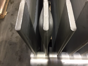
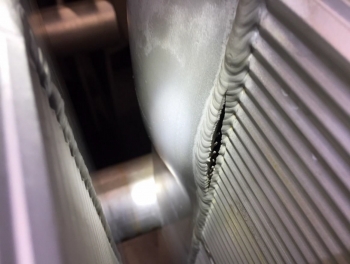
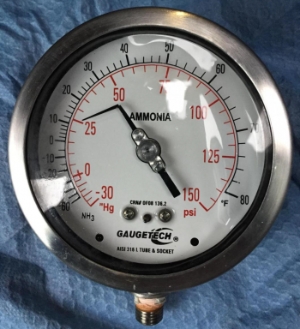
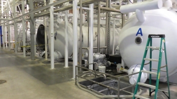
The responding refrigeration mechanic stated he attempted to improve system performance by closing valves to generate pressure within an evaporator to move or dislodge potentially trapped oil. The pressure rose very rapidly once the evaporator was isolated between closed valves, breaking a pressure gauge needle (photo 3) and rupturing the evaporator (photos 1 and 2).
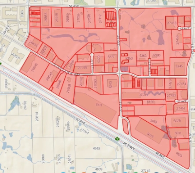
An estimated 485 to 1,500 lbs of ammonia was released from the ruptured evaporator into the freeze-drying production chamber. The chamber is not designed to contain ammonia and therefore ammonia escaped the chamber into the atmosphere. There was no provision for ammonia extraction from the chamber. As a result a significant volume of ammonia entered into the chamber and could not be quickly removed. The release resulted in an extensive area being evacuated for two days (Diagram 1) while the leaked ammonia was dispersed into the atmosphere and contained within a water solution.
Regulated Industry Sector
Refrigeration – Boilers and Pressure Vessels
Location
Langley
Investigation Conclusions
Site, System and Components
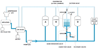
The refrigeration system is depicted in Diagram 2, consisting of four operating chambers (A, B, C and D) and three flash freezers. Liquid ammonia was pumped to the chambers and freezers to remove heat and moisture. Ammonia was returned to high pressure and low pressure receivers (LPRs) via compressor suction and liquid pump pressure. The total refrigerant charge of the system was identified as 9,500 lbs of ammonia.
The LPR incorporated an oil trap to remove compressor oil prior to circulation of the liquid ammonia to the pumps and heat exchangers. Compressor oil is heavier than liquid ammonia and will settle at the bottom of the receiver vessels where oil traps are located or at low points in system piping. Oil from the oil pot would be removed at regular maintenance intervals to prevent accumulation and circulation throughout the refrigeration system. Oil drainage provisions were incorporated at system piping low points located at each chamber.
A maintenance program will establish and monitor oil removal and management activities. If oil is allowed to accumulate within the vessel, it will eventually contaminate the liquid ammonia flowing into the system.
At very low temperatures consistent with that of liquid ammonia, compressor oil viscosity is high and the oil may not flow or move easily through the system or components. Excessive oil in the ammonia system can reduce ammonia flow and interfere with mechanical motion (pumps). The effects can be reduced performance or the generation of system / component faults from monitoring circuits.
Liquid ammonia is metered into the evaporators within each chamber by a hand expansion valve as shown in Diagram 2. The hand expansion valves are set at the desired operating point during system commissioning and not intended to be adjusted during normal operation. The operating point associated with the hand expansion valve will correspond to a ratio of liquid refrigerant to total volume. Typically, a steady state operating evaporator’s set point corresponds to approximately 50% of the volume being liquid refrigerant within an evaporator.
Ammonia has a relatively high liquid expansion coefficient. It is important to never trap liquid ammonia inside a vessel or between valves without a significant portion of vapour volume present to allow for expansion. With small temperature changes, trapped liquid can cause a rapid and significant pressure increase.
Please see attached PDF for full report including:
- Appendix A: AFD Canature Investigation Cold Dynamics
- Appendix B: Cold Trap Failure Analysis: Canature Processing Ltd, Langley BC ACUREN Group Inc.
Failure Scenario(s)
Oil was not being sufficiently removed from the refrigeration system following a change in compressor output setting. On October 23, 2018, an overload failure of the ammonia pump occurred and was suspected to be a result of oil contamination. Once service was restored to the refrigeration system, performance of the evaporators was suspected to be affected by oil contamination.
The evaporator at one of the chambers was being supplied through a hand expansion valve set to the full open position, leading to a condition where liquid ammonia had flooded the evaporator and associated piping. Troubleshooting of the evaporator performance included isolating the component between valves, without pumping down the liquid ammonia.
The isolation of liquid ammonia caused an overpressure condition to rapidly develop, rupturing the evaporator at a location of high stress and a manufacturing defect.
Facts and Evidence
Compressor Oil Migration and Maintenance
- Owner/Operator stated that compressor output temperature/pressure setting was increased shortly after commissioning in 2015 to improve oil separation. Oil migration into the system was communicated to be problematic and causing upsets such as liquid ammonia pump contamination and overload tripping.
- Owner/Operator stated that compressor output temperature/pressure setting was reduced a few months prior to the incident to save energy.
- Maintenance log shows the following:
- Weekly LPR oil pot drainage task – typically removes 10 litres oil
- Oct 11 – 12 litres oil removed from LPR oil pot
- Oct 12 – 38 litres of oil drained from chamber D evaporators and associated piping (located adjacent to failed chamber C)
- Oct 18 – 20 litres oil removed from LPR oil pot with the following note added: *THIS AMOUNT IS MUCH MORE THAN PREVIOUS WEEKS
- The following volumes of oil were removed from the chambers following the incident:
- Chamber A: 15 litres
- Chamber B: 10 litres
- Chamber C (contains failed evaporator): 20 litres
- Chamber D: 1-2 litres (in addition to the 38 litres drained on Oct 12)
- Owner/Operator stated that they did not believe the evaporators had been drained of oil since entering service and were not aware that 38 litres was reported drained by an employee from chamber D on October 12.
- Owner/Operator stated that they were not aware of changes to the amount of oil drained by employees from the oil pot on October 11 and 18 or the recorded notes in the maintenance logs.
- Refrigeration mechanic stated that he did not consult maintenance or operator logs and had not been informed of changes to the oil removal volumes or the volume of oil removed from the adjacent chamber D on October 12.
- Refrigeration mechanic stated that he normally only interacted with facility managers and did not interact with the chief engineer or employed power engineers.
- Owner/Operator stated that there was no designated chief engineer during the months leading up to the incident however there are a number of 4th class power engineers assigned to maintenance and operations.
- Owner/Operator stated that the mechanic arrived on site at approximately 9:20pm to drain oil from the ammonia pumps and restore system operation.
Conclusion 1:
Evidence existed that an increase in compressor oil migration was occurring. There was no evidence that changes were made or being planned to the maintenance program, to correct the problem or prevent the effects of increased oil migration.
Valve Settings and Manipulations
Troubleshooting and pre-rupture
- The refrigeration mechanic stated that the hand expansion valves had been set at approximately 3.5 turns in the open position during commissioning as instructed by the design engineer.
- Refrigeration mechanic stated he closed one hand expansion valve to the chamber C cold trap to confirm an upstream pressure increase and liquid flow into the cold trap.
- Refrigeration mechanic stated he recalled that the hand expansion valves were in the ‘wide open’ position and required an estimated 10 turns to close.
- Refrigeration mechanic stated that he returned the hand expansion valve to the found operating position of ‘wide open’.
- Refrigeration mechanic stated that management asked to drain oil from the cold traps but mechanic explained that it was not possible because of the vacuum condition and liquid ammonia present in the cold trap.
- Refrigeration mechanic stated that at the request of management, an attempt was made to temporarily increase the pressure within the evaporator with the use of the suction valve.
- Refrigeration mechanic stated both hand expansion valves were closed followed by closing the suction valve to achieve the pressure increase. It is estimated that approximately five to eight minutes elapsed between the closing of these valves, which occurred at approximately 1:30am on October 24, 2018.
- Refrigeration mechanic stated that both hand expansion valves feeding the chamber C cold trap were in the ‘wide open’ position prior to their closing.
- Owner/Operator and refrigeration mechanic stated that two of the three chambers were reported to be slow returning to operating performance following the removal of oil and servicing of the ammonia pumps. The subsequent actions associated with manipulating hand expansion and suction valve of chamber C were in response to suspected oil contamination of the evaporators from this inhibited performance.
- Owner/Operator and refrigeration mechanic reported that chamber C troubleshooting during mid-cycle operation was motivated by an interest in saving the batch of product that had remained in the chamber throughout the pump maintenance procedure.
Post-rupture
- Refrigeration mechanic stated that the suction valve was immediately reopened following rupture in an attempt to pump out any remaining ammonia from the cold trap.
- Refrigeration mechanic stated the liquid supply valve was closed and the hand expansion valves re-opened. The refrigeration mechanic did not recall the order of these two operations. It is possible that additional liquid ammonia was supplied into the failed cold trap.
- The suction valve was re-closed approximately 20-30 minutes following the rupture upon recognition that the vacuum in the chamber was at a lower pressure, pulling additional ammonia vapour into the chamber from the system.
Conclusion 2:
Suspected oil contamination of the evaporators motivated system performance troubleshooting efforts during operation.
Conclusion 3:
The system was being operated with hand expansion valves fully open, contrary to design specifications which resulted in the evaporator becoming flooded with ammonia and left no room for expansion.
Conclusion 4:
It is likely that additional ammonia trapped between the liquid feed valve and suction valve was released into the chamber during the time the suction valve was re- opened and during the re-opening of the hand expansion valves.
Standard Operating Procedures (SOPs)
- There were no SOPs identified specific to the procedure being attempted to move or dislodge suspected trapped oil within evaporators during operation.
- A SOP existed for removal of oil from the evaporator titled “Cold Trap Oil Drain SOP”
- Managers who were supervising the refrigeration mechanic stated they were unaware of the existence and content of the SOPs prior to the incident.
- The SOP for the removal of oil, while not applicable to the procedure being attempted, contained relevant information about the potential hazards:
- provides the following statements: Potential HAZARDS: Improper operation could cause severe damage to cold trap and piping due to excessive pressure built up inside cold trap and associated system components.
- provides instructions to pump down the system prior to closing the suction valve
- The refrigeration mechanic stated he was not made aware of or provided any training relative to the SOPs and had never performed the cold trap oil drain task.
- Owner/Operator stated they deferred to the guidance of the refrigeration mechanic given their qualification and familiarity with the system.
Conclusion 5:
There was no designated chief engineer for the facility at the time of the failure and there was no effective chief engineering function at the facility. One important function of the chief engineer is to facilitate the work of onsite contractors and the knowledge of developing maintenance issues. Knowledge of site or system specific hazards, such as those contained in facility SOPs, may be considered during troubleshooting.
System Design and Assessment
- No automatic over-pressure protection was provided for the evaporators. The Mechanical Refrigeration Code CSA B52-13 requires over-pressure protection in certain circumstances. The two most relevant circumstances relate to maintenance, where unspecified controls are required (7.2.4.3) or evaporators where a heat source is in close proximity (7.3.2.1).
- It was reported that designers may consider awareness and training of maintenance personnel as a means of control to prevent hydrostatic over- pressure, in compliance to 7.2.4.3 of CSA B52-13.
- The system designer stated that no pressure relief was provided because the potential heat sources did not meet the requirements in CSA B52-13 7.3.2.1 for pressure relief.
- No lock-outs or other preventative methods were in use to prevent the adjustment of hand expansion valves following commissioning.
- No maintenance signs were posted near the hand expansion valves or the suction valve to provide caution to employees or contractors concerning the trapping of liquid ammonia although warning of potential evaporator failure were included in the oil drainage SOP.
- Assessment of the system included in Appendix A, AFD Canature Investigation by Cold Dynamics Ltd. concludes:
- If operated at design conditions, isolating the evaporators as occurred prior to the incident should not have produced a concerning liquid expansion scenario.
- Risk factors including operating with the hand expansion valves wide open led to a flooded condition between the two sets of valves.
- The flooded condition could have resulted in a rapid and substantial pressure rise, reaching pressures in the order of 10,000 psi.
- The amount of liquid that could have been contained between the liquid feed valve and the suction valve was approximately 485 lbs.
- The amount of ammonia added to the system following the event was reported to be 1,000 lbs. The amount of ammonia in the system prior to the event was not known.
- An estimated 2,500 litres of solution (ammonia and water) was observed via frost lines on the chamber following the release.
Conclusion 6:
There was a reliance upon maintenance awareness and contractor qualification for over-pressure protection. Signage or lock-outs, while not typical for the refrigeration industry, were not used to warn of or prevent opening the hand expansion valves or provide pump down caution prior to closing the suction valve.
Conclusion 7:
Closing the hand expansion and suction valves when the system is operating as designed and commissioned would likely have not resulted in the incident.
Conclusion 8:
The amount of ammonia released during the event was between 485 and 1,500 lbs. See Appendix A for analysis.
Gauge examination and testing
An examination of the failed pressure gauge (Photo 3) and testing of an exemplar gauge is documented in Appendix B, Cold Trap Failure Analysis by Acuren Group Inc., and concludes:
- Failure of the pressure gauge was due to a rapid pressure increase.
- The failed pressure gauge was subjected to pressure in excess of 700 psi.
Heat exchanger (cold trap) examination and testing
An examination and testing of the failed evaporator (Photos 1 and 2) is documented in Appendix B, Cold Trap Failure Analysis by Acuren Group Inc., and concludes:
- Failure is due to overload that led to bulging and ductile tearing of the cold trap header attachment welds.
- Failure occurred in an area of the evaporator plate structure that was an area of high stress and also weakened due to drilling defects.
- Pressure required to produce the material failure was 10,000 psi.
Conclusion 9:
The evaporator material failure was due to structural overload, consistent with an over-pressure condition.
Conclusion 10:
The system pressure rise was rapid and may have reached 10,000 psi.
Causes and Contributing Factors
Rupture of the evaporator and release of ammonia was caused by an overpressure condition. The overpressure condition developed as a result of trapping an excessive volume of liquid ammonia between valves.
The overpressure condition was a result of the following factors:
- Failure to effectively mitigate oil migration, respond to changes in oil migration and remove migrated oil from the refrigeration system led to the unusual actions to attempt to bring the system back to normal performance.
- Operation of the system with the hand expansion valve fully open caused the system to be fully flooded between the hand expansion valves and suction valves.
- Closing the suction valve without pumping down the liquid ammonia level from the evaporator increased the risk hydrostatic expansion.
- No effective chief engineer to oversee maintenance trends, system performance, troubleshooting and adherence to procedures by contractors caused oil migration conditions to not be understood by management.
- Lack of methods to promote awareness or prevention of a hydrostatic over- pressure condition led to no consideration of the consequences to the system of manipulating the hand expansion valves or the suction valve beyond normal operating conditions.
Impact
- Injury
- Qty injuries: 0
- Injury description: N/A
- Injury rating: N/A
Damage
- Damage description: Ruptured evaporator (also referred to as heat exchanger or cold trap) released estimated 485 to1,500 lbs of ammonia from refrigeration system and resulted in an extensive area evacuation for two days.
- Damage rating: Major
- Incident rating: Major
Diagram 1: Evacuation area enforced and communicated by the Township of Langley while responding to the ammonia release. Affected area is industrial and the evacuation was enforced for approximately 48 hours from October 24th through October 26.