Electric Drive Upgrades for Passenger Ropeways and Passenger Conveyors
Information Bulletin
Electric Drive Upgrades for Passenger Ropeways and Passenger Conveyors
June 19, 2023
Reference Number:
IB-PR 2023-01
Topic:
Guidelines and design considerations for ELECTRIC DRIVE UPGRADES for Passenger Ropeways and Passenger Conveyors.
Background:
There have been recent serious incidents resulting from unintended consequences of drive system upgrade failures.
Because of these failures, a Passenger Ropeway and Passenger Conveyors Industry Task Force, made up of members from across Canada, completed a review and assessment of current requirements. The Task Force created a two-part SAFETY ALERT for Passenger Ropeway and Passenger Conveyor Drive Upgrades, establishing a GUIDELINE of Technical Information and Design Considerations to be used in support of CSA Z98 Passenger Ropeways and Passenger Conveyors Standard (current adopted edition).
Technical Safety BC (TSBC) is responsible for safety oversight of Passenger Ropeways and Passenger Conveyors and believes the SAFETY ALERT provides an acceptable GUIDELINE for consideration as part of a Passenger Ropeway and Passenger Conveyor Electric Drive Upgrade in British Columbia.
In British Columbia, the adopted standard for passenger ropeways and passenger conveyors is the CSA Z98:14 (2014) edition. The SAFETY ALERT document in this bulletin references the most recent publication of the CSA Z98 standard which is the 2019 edition. Any electric drive upgrades for passenger ropeways and passenger conveyors must meet the requirements of the Z98:14 standard.
Electric drive upgrades for passenger ropeways and passenger conveyors are considered major alterations which require the submittal of a technical information package as specified in section 25 of the Elevating Devices Safety Regulation (EDSR). The professional engineer submitting the technical information package should consider the applicable items listed in the SAFETY ALERT – Part 2 design considerations, when completing the technical design.
See below for the SAFETY ALERT.
Nav Chahal,
Provincial Safety Manager - Transportation
References:
Safety Standards Act
Elevating Devices Safety Regulation
NOTE: This is a GUIDELINE ONLY and is not intended to eliminate or diminish any adopted standards, regulations or legislative requirements.
Safety Alert – Part 1 – General Overview - Passenger Ropeway and Passenger Conveyor Electric Drive Upgrades
(See Also Part 2 – Technical Information and Detailed Explanation)
1. SCOPE
This safety alert is intended to guide owners, managers, operators, suppliers, designers, authorities, and persons contemplating or implementing a passenger ropeway or passenger conveyor electric drive upgrade. The need arises from recent serious incidents resulting from unintended consequences of drive system upgrades. This safety alert consists of two parts (Part 1 – General Overview and Part 2 – Technical Information and Detailed Explanation).
Part 1 provides a brief overview. Part 2 provides important design considerations.
This safety alert is applicable to the following categories of passenger ropeways and passenger conveyors:
- reversible passenger ropeways with single- or double-track ropes;
- fixed and detachable grip circulating above-surface monocable, bi-cable, and tri-cable ropeways, including cabin ropeways, chair ropeways, and similar devices;
- surface ropeways, including T-bar ropeways, J-bar ropeways, platter ropeways, and similar devices; and
- passenger conveyors.
Drive systems are often referred to as “motor controllers.” There are many older drive systems presently in use. It is believed that many will require upgrades within the next few years. This safety alert is intended to prevent serious incidents by providing advice to those involved in drive upgrades.
2. CONTENTS
This safety alert provides insight into:
- drive upgrade skill sets;
- professional association guidelines;
- regulations;
- professional qualifications;
- basic safety;
- redundancy, monitoring, and supervision;
- brakes;
- harm and risk reduction;
- risk or hazard analysis;
- failure modes;
- contactors; and
- pitfall avoidance.
3. BACKGROUND INFORMATION
Passenger ropeways and passenger conveyors generally utilize commercially available drive systems. These drive systems are used in thousands of different applications, and therefore need to be specifically customized for each application. Passenger ropeways and passenger conveyors have unique and specific requirements that are only understood by qualified persons that are properly educated, trained, and experienced in this industry. Drive system specialists may not be familiar with critical interdependencies between passenger ropeway and passenger conveyor controls and equipment and the drive system. The work should be performed according to professional practice guidelines for safety-critical or high-risk work.
Drive upgrades are usually considered to be safety-critical systems and “major alterations.” Safety-critical system designs should have adequate professional documentation and documented independent expert professional review. Electrical schematics and documentation (including parameter settings) will need updating and correction as required.
Passenger ropeways and passenger conveyors are regulated by various provincial authorities having jurisdiction (AHJ). The appropriate authority should be consulted to determine the compliance requirements. Generally, upgrades will need to comply with CSA Z98 (adopted edition as per each Province) Passenger ropeways and passenger conveyors standard and CSA C22.1 Canadian Electrical Code as adopted by the AHJ and may require design submissions and field inspections.
4. GUIDELINES FROM PROFESSIONAL ENGINEERING ASSOCIATIONS
- PROFESSIONAL PRACTICE GUIDELINES FOR DEVELOPMENT OF SAFETY-CRITICAL SOFTWARE 2020-07-16
- GUIDE TO THE STANDARD FOR INDEPENDENT REVIEW OF HIGH-RISK PROFESSIONAL ACTIVITY OR WORK 2021-04-27
- PRACTICE ADVISORY – RELYING ON THE WORK OF A SPECIALIST 2021-07-22
- PROFESSIONAL PRACTICE STANDARD – RELYING ON THE WORK OF OTHERS AND OUTSOURCING
These are available at the following links:
- https://www.egbc.ca/app/Practice-Resources/Individual-Practice/Guidelines-Advisories
- https://www.egbc.ca/Practice-Resources/Individual-Practice/Quality-Management-Guides
- https://www.apega.ca/docs/default-source/pdfs/standards-guidelines/relying-on-the-work-of-others-and-outsourcing.pdf
Similar guidelines and standards are available from other provincial engineering associations. It is important to recognize “software life cycles” and to fulfill software maintenance guidelines with respect to ongoing maintenance of software “health,” handling of defects, changes, and updates to third-party software, changes to support tools and security vulnerabilities.
5. REFERENCED STANDARDS (https://www.csagroup.org/store/)
- CSA Z98:19 PASSENGER ROPEWAYS AND PASSENGER CONVEYOR STANDARD CSA C22.1 CANADIAN ELECTRICAL CODE, PART 1 (SAFETY STANDARDS FOR ELECTRICAL INSTALLATION)
- CSA C22.2 CANADIAN ELECTRICAL CODE, PART 2 (ELECTRICAL PRODUCT STANDARDS)
- CSA Z98:19 Passenger ropeways and passenger conveyors standard contains important Annex L (Notes on Clauses) that helps to explain many relevant design safety considerations pertaining to drive systems. Drive system upgrade designers need to be aware of these safety concepts.
6. QUALIFICATIONS
Only qualified persons familiar with hazards associated with specific types of passenger ropeways and passenger conveyors should be responsible for drive upgrade designs. The manufacturer should be involved, where appropriate, and this involvement should commence very early in the project. A qualified registered professional engineer should be responsible for designs, design checks, design reviews, inspections, commissioning, testing, certification, and documentation. Upgrading a drive system will likely result in serious unintended consequences unless the persons and suppliers involved are competent and qualified to safely carry out the work.
7. OLDER DRIVE SYSTEMS
Upgrades generally apply to older drive systems. Older drive systems are not usually involved in braking. Older drive systems generally rely exclusively on mechanical braking and ropeway controls have limited redundancy, monitoring, and supervision capabilities. Older drive systems generally have simple interfaces with the ropeway controls. Older drive systems generally rely on a mechanical contactor to disconnect the drive motor and/or the ac supply.
In general, if the ropeway controls will not become part of the upgrade, the new drive system should perform as near as possible to the performance and capabilities of the old drive system or else the ropeway controls should be upgraded to suit the requirements of the new drive system. Older analog drive systems make it difficult or impossible to copy or simulate the old parameters in the new drive system.
Newer drive systems are often involved in braking. Such drive systems present several hazards that need to be considered. In general, if an upgrade introduces a change wherein the drive becomes involved in braking, older ropeway controls that rely upon mechanical braking will need to be completely replaced to achieve the required redundancy, monitoring, and supervision.
If the drive upgrade will be involved in braking, then there are numerous complicated safeguards necessary to independently monitor the drive system and to quickly take remedial action when something goes wrong. Consequences of safety function failure determine the scope and reliability of the system necessary to reduce the risk of injury or damages to within acceptable limits. It is intended that the control system be designed according to a recognized international design standard. These standards provide systematic frameworks for identifying safety functions, identifying, and assessing hazards and risks, categorizing performance levels and safety levels, identifying methods to achieve appropriate risk reduction levels, and assigning performance and safety levels to safety functions.
Unfortunately, a textbook approach to design is not possible. Each upgrade presents a unique set of hazards, depending on the equipment configuration, load cases, control system, drive system product, motor size and type, etc.
Safety Alert – Part 2 – Technical Information and Detailed Explanation – Passenger Ropeway and Passenger Conveyor Electric Drive Upgrades – (See Also Part 1 – General Overview)
8. SCOPE
This safety alert is intended to guide owners, managers, operators, suppliers, designers, authorities, and persons contemplating or implementing a passenger ropeway or passenger conveyor electric drive upgrade. The need arises from recent serious incidents resulting from unintended consequences of drive system upgrades. This safety alert consists of two parts (Part 1 – General Overview and Part 2 – Technical Information and Detailed Explanation).
Part 1 provides a brief overview. Part 2 provides important design considerations. Part 2 should not be relied upon as a comprehensive and complete list of design requirements.
9. BASIC SAFETY REQUIREMENTS
Safety requirements considered relevant to this discussion can be found in CSA Z98:19 Passenger ropeways and passenger conveyors in Clauses 4.31.1.7, 4.31.1.8, 4.31.1.10, and 12.8.1.
10. DRIVE SYSTEM REDUNDANCY, MONITORING, AND SUPERVISION
Where a drive system is involved in braking, multiple levels of increased redundancy, monitoring, and supervision are necessary to ensure that the drive system performs properly. In this case, the following monitoring functions should be provided:
- acceleration monitoring;
- deceleration monitoring;
- torque or current monitoring;
- speed monitoring;
- zero speed monitoring (as applicable);
- speed feedback monitoring and comparison;
- torque or current surge monitoring;
- overspeed monitoring (dc motors);
- field loss monitoring (dc motors);
- processor stall monitoring (i.e., “watchdog”);
- armature overcurrent monitoring (dc motors); and
- armature overvoltage monitoring (dc motors).
The drive system should be designed to have redundant commands to start and continue running. For example, both “RUN” and “SAFETY CIRCUITS OK” conditions are needed. Loss of either will cause the drive to stop. Similarly, drive systems should be designed to have redundant stop commands. For example, either a “STOP” or “EMERGENCY STOP” command will stop the motor. The drive can be stopped by stopping the SCR (silicon-controlled rectifier) bridge or IGBTs (insulated gate bipolar transistors). With a safe torque off (STO) function that is adequately safety rated, the ac motor can be safely disabled by disconnecting the control voltage to the IGBTs. With SCRs, switching off the firing circuit does not prevent an SCR from a short circuit that will energize the armature. Therefore, the only reliable way to disable a dc motor is to open either the main contactor on the ac supply side or a dc contactor feeding the armature (or a lockable manual disconnect).
11. BRAKES
It might be necessary to provide conditional braking controls to take necessary remedial action according to the type of fault or failure, including loss of the ac supply. For example, various independent braking systems might be required as specified by the ropeway designer/ manufacturer in accordance with the CAN/ CSA Z98:
- System 1: Electrical stopping with the main drive motor.
- System 2: Braking with the service brake (friction brake) (typically on the drive line).
- System 3: Braking with the emergency brake (friction brake) (typically on the drive sheave).
System 2 and/or 3 can be electrically stepped, hydraulically stepped, or modulated. Application of System 2 and/or 3 safely switches off the main drive motor. For example, possible stopping types (TS) can be provided:
- TS1: STOP: System 1
- TS2: EMERGENCY STOP: System 1 (with faster deceleration)
- TS3: EMERGENCY STOP WITH SERVICE BRAKE: System 2
- TS4: EMERGENCY STOP WITH EMERGENCY BRAKE: System 3
- TS5: EMERGENCY STOP WITH SERVICE BRAKE + EMERGENCY STOP WITH EMERGENCY BRAKE: Systems 2 and 3 (simultaneous)
The system needs to be capable of transitioning from one stopping type to another, depending on the real-time deceleration monitoring function. For example, in case of inadequate deceleration by:
- TS1 transition to TS3 (electrical stepping, hydraulic stepping, or modulation active).
- TS2 transition to TS5 (electrical stepping, hydraulic stepping, or modulation active).
- TS3 transition to TS5 (electrical stepping, hydraulic stepping, or modulation active).
- TS4 transition to TS5 (electrical stepping, hydraulic stepping, or modulation active).
- TS5 (electrical stepping, hydraulic stepping, or modulation active) transition to TS5 (without stepping or modulation).
Due to the overlapping time function, the stepping or modulation function needs to be switched off after an adjustable time limit has elapsed.
The system needs to be capable of prioritizing types of stops when multiple stop commands occur together.
| For example: Priority order (when 2 commands arrive) | TS1 | TS2 | TS3 | TS4 | TS5 |
| STOP > E-STOP | X> | X | |||
| STOP > E-STOP WITH S-BRAKE | X> | X | |||
| STOP > E-STOP WITH E-BRAKE | X> | X | |||
| E-STOP > E-STOP WITH S-BRAKE | X> | X | |||
| E-STOP > E-STOP WITH E-BRAKE | X> | X | |||
| E-STOP WITH S-BRAKE > E-STOP WITH E-BRAKE | X> | X | |||
| E-STOP WITH E-BRAKE > E-STOP WITH S-BRAKE | X> | X | |||
| E-STOP WITH S-BRAKE > E-STOP | X> | X | |||
| E-STOP WITH E-BRAKE > E-STOP | X> | X |
12. STRATEGIES FOR HARM AND RISK REDUCTION
A programmable logic controller (PLC) generally executes a sequence of commands to evaluate inputs and set outputs. If the number of steps becomes too large for the processor speed, a PLC will be unable to react quickly enough in an emergency. Semiconductor devices are common because of cost, assembly time, and time for testing and troubleshooting. Knowing semiconductors have unpredictable failure modes, robust countermeasures to achieve adequate safety and reliability are needed. There are various strategies to accomplish this:
- redundant duplicate or triplicate circuits to compensate for single-point failures
- clocked signals sent through switching devices to ensure that the input is “seeing” a legitimate signal from the device
- certified safety rated devices
- force-guided safety relays with contacts that cannot weld shut or fail to close without faulting the circuit
- relays oriented so that they open rather than close by gravity if their spring mechanisms fail
- independent redundant monitoring of safety functions
- functions in parallel (e.g., pressure transducers in parallel with pressure switches)
- robust hardware materials, wiring methods, and equipment architecture
- appropriate routine testing methods and intervals
- self-testing capabilities
- fault tolerant designs
- organized command sequencing and command supervision
13. RISK OR HAZARD ANALYSIS
Risk is the combination of the probability of occurrence of harm and the severity of that harm. For example, consider the rope tension monitoring system. For some passenger ropeways, if the carriage unintentionally moves all the way to the forward stops, the drive sheave will not provide enough friction and the haul rope will slip, depending on load. This could create a potentially catastrophic outcome. In other passenger ropeways, the drive sheave will always have enough friction, no matter where the tension carriage is located. Risk analysis will determine how circuits need to be designed according to the probability and consequences of the most adverse outcome of potential loss of safety function.
A simple method to provide redundant haul rope tension monitoring is to monitor both tension carriage position and tension pressure or force.
Where the tension pressure is provided by an electric pump, overpressure monitoring is needed, since a runaway pump, or failed relief valve, can cause an unsafe condition. Where the tension pressure is provided by a hand pump (e.g., small surface lift), overpressure monitoring is not needed if the hand pump cannot produce enough pressure to cause damage.
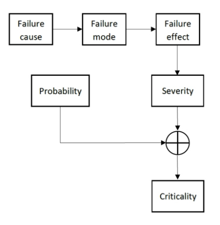
The following terminology from IEC 60812 Analysis Techniques For System Reliability – Procedure For Failure Mode And Effects Analysis (FMEA) Ed. 2.0 2006 : are applicable:
- Failure cause: why did the item fail.
- Failure mode: manner in which the item fails.
- Failure effect: consequence of a failure mode in terms of the operation, function, or status of an item.
- Failure severity: significance or grading of the failure mode’s effect on item operation, on the item surrounding, or on the item operator; failure mode effect severity as related to the defined boundaries of the analyzed system.
- Failure criticality: combination of the severity of an effect and the frequency of its occurrence or other attributes of a failure as a measure of the need for addressing and mitigation.
- FMEA: failure mode and effect analysis.
Failure mode and effects analysis (FMEA) is one effective method often used to help determine safety levels according to probability and consequences of failure.
The following is an example of categories that might be considered:
The following is an example of categories that might be considered:
| 1 | Well tried | Using proven components according to industry practices |
| 2 | Checked | Using proven components and safety principles |
| 3 | Redundancy | A single fault must not cause loss of safety function(s). Safety functions are to be tested at suitable intervals – “first fault” theory. |
| 4 | Self-monitoring | A single fault must not cause loss of safety function(s). An accumulation of faults must not cause loss of safety function(s). The faults must be detected in time to prevent loss of safety function(s). – “second fault” theory. |
The allocation of the individual safety functions to the necessary categories is carried out using a risk or hazard analysis. When examining faults, it is important that all components — not just the controls, but also the switching components and effective components — are considered in the safety analysis. It is important that safety principles are applied when designing the controls. The overall design configuration needs to be done correctly to benefit from the safety rating of the individual components.
The control system should be designed according to a recognized international design standard, such as:
- EN 13223 — Safety requirements for cableway installations designed to carry persons — Drive systems and other mechanical equipment.
- EN 13243 — Safety requirements for cableway installations designed to carry persons — Electrical equipment other than for drive systems.
- ISO 13849 — Safety of machinery — Safety-related parts of control systems.
- IEC 62061 — Safety of machinery — Functional safety of safety-related electrical, electronic, and programmable electronic control systems.
- IEC 61508 — Functional safety of electrical/electronic/programmable electronic safety related systems.
- ANSI B77 — Aerial tramways, aerial lifts, surface lifts, tows, and conveyors safety requirements.
These standards provide systematic frameworks for identifying safety functions, identifying, and assessing hazards and risks, categorizing performance levels and safety levels, identifying methods to achieve appropriate risk reduction levels, and assigning performance and safety levels to safety functions.
It is intended that the performance of safety-related control functions should be specified relative to the level of corresponding risk being controlled. Each of these standards provides a logical process for estimating risk and defining a suitable level of performance for each applicable safety-related control function.
14. FAILURE MODES
Control systems are subject to component failures that can lead to loss of control and loss of safety, especially digital control systems. Modern drive systems typically use single-channel processors which are subject to:
- sudden, unpredictable failure of semiconductors (diodes, SCRs, IGBTs, transistors, etc. which can fail either on or off)
- processor input/output failure (I/O failure)
- processor stall (freeze or lock-up)
- signal communication failure
- binary memory failure (one or zero)
- systemic programming errors
- faulty circuit logic
Safety circuits should be designed to provide safety levels corresponding to the probability and consequences of failure. This general design methodology was originally targeted at failure modes arising primarily from semiconductor devices. However, the same approach applies to all safety-related control functions, with or without semiconductor devices.
15. CONTACTORS
Drive systems should be designed to have robust and independent direct control of the contactor (for example, fail-safe computer output with redundancy). It is also important to reliably monitor the contactor position to see if it is open before it can be closed. This check requires redundant tests. A main contactor controlled by a single drive processor digital output cannot generally be relied upon to function safely. To protect against loss of control, in most cases it is necessary for the safety monitoring to be performed by a system that is independent of the drive. Furthermore, a main contactor should be provided, and it should be controlled by a system that is independent of the drive (safe torque off (STO) available in some ac drives is considered equivalent, provided it is adequately safety rated). The contacts that control the contactor should be redundant, so that the failure of a single contact cannot defeat the safety function.16. EXAMPLES OF POSSIBLE DESIGN ERRORS
Unfortunately, a textbook approach to design is not possible. Each drive upgrade presents a unique set of hazards, depending on the equipment configuration, load cases, control system, drive system product, motor size and type, etc. To help explain possible pitfalls in the design process, here are practical examples of possible design flaws.
16.1 Parameter settings
Commercially available drive systems are equipped with firmware in the programmable logic controller that enables the drive system to fulfill a multitude of different applications. This firmware is parameter driven. Hundreds of different parameters are available to tailor drive performance. Some have major influence, and some have minor influence.
Typically, there is a parameter to limit the forward and reverse current limits and forward and reverse torque limits. In general, the drive only supplies adequate torque and current to do the job. But in the event of a malfunction, if these limits are set unnecessarily high, the drive system could cause catastrophic damage from a sudden surge in torque and current.
This is only one example. A partial list of other important parameters include:
- rates of acceleration
- rates of deceleration
- motor nameplate voltage
- motor nameplate current
- nominal supply voltage
- speed feedback loss
- supply voltage ripple
- brake release current
- zero speed level
- field weakening level (if applicable)
- overspeed trip
- fly start (if applicable)
- motor overload
16.2. Acceleration and deceleration
During speed transitions, the drive system follows programmed acceleration or deceleration curves. These curves are either programmed through drive system parameters or provided by an external signal. These curves are usually selectable. For example, the normal stop deceleration curve might be different than the emergency stop deceleration curve. A transition from stop to full speed might follow a different rate than a transition from full speed to a preset medium speed. If the speed change rates are abrupt, then a series of rapid speed changes could result in unintended rope bounce with resulting carrier swing.
16.3. Acceleration and deceleration monitoring
If the drive is involved in braking, the actual speed vs. acceleration/deceleration time curve needs to be closely monitored to ensure rates always remain within allowable envelopes. The system must react quickly to always maintain safe conditions. In addition, suitable safeguards are necessary to verify that the relied upon speed signal is accurate (for example, comparing rope speed, reference speed and motor speed).
16.4. Contactor control
Many commercially available drives use a single channel output to control the contactor. Sometimes a communication link such as fibre optic or ethernet is relied upon to communicate contactor commands. These methods are not seen to provide adequate safety for passenger ropeway and passenger conveyor applications. Generally, it is best if the contactor uses a “failsafe” computer output or monitored redundant devices with similar safety level.
16.5. Autotuning
The current controller in a drive system typically uses feedback loop logic that monitors the speed error (actual vs. reference) to control motor torque. This feedback loop is parameter driven to control response time and stability. The selection of these parameters is referred to as “tuning” the drive. If this is not done properly, the current controller can become unstable with catastrophic loss of speed control and resulting rope bounce. If the acceleration/deceleration monitor is set up correctly, it should detect and correct the problem. In any case, the drive should be properly tuned by an individual with the appropriate skills and experience. Tuning is also important in cases where the chair spacing resonates with the tower spacing, resulting in line surging. Motor rebuilds can sometimes require drive re-tuning.